Jak działają kamery do inspekcji otworów wiertniczych w warunkach geotechnicznych
Podstawowe zasady obrazowania rdzeni i przepływ pracy z wizualizacją w czasie rzeczywistym wewnątrz otworu wiertniczego
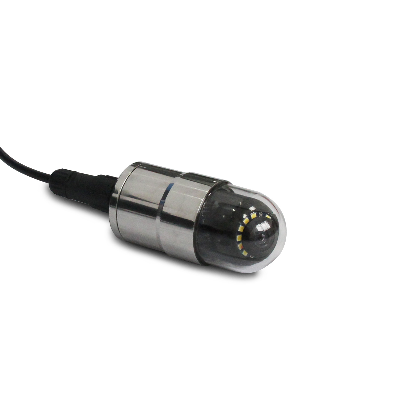
Kamery inspekcyjne do otworów wiertniczych działają poprzez wprowadzanie do otworu sondy wyposażonej w czujnik typu CCD lub CMOS oraz jasne diody LED zamontowane na specjalnie oznakowanej kabelce. W miarę jak sonda opuszcza się w głąb otworu, obraz w czasie rzeczywistym pojawia się na monitorach na powierzchni gruntu. System ten umożliwia również dokładne określenie położenia poszczególnych elementów pod ziemią dzięki wbudowanym urządzeniom pomiaru głębokości. Takie rozwiązanie pozwala inżynierom natychmiast wykrywać problemy, takie jak pęknięcia w ścianach otworu, nagromadzenie brudu i zanieczyszczeń lub zaczynające się osuwanie jego ścian – wszystko to bez konieczności pobierania próbek przez wykopanie gruntu. Aby uzyskać najbardziej wyraźne obrazy, operatorzy tych systemów dostosowują częstotliwość odświeżania klatek na ekranie oraz zmieniają jasność oświetlenia w zależności od mętności wody i rzeczywistej średnicy otworu. Takie korekty pozwalają utrzymać wysoką jakość obrazu nawet przy pracy w różnych typach gleb i formacjach skalnych.
Kluczowe specyfikacje zapewniające niezawodność geotechniczną: rozdzielczość, wydajność w warunkach niskiej oświetlenia, kompensacja nachylenia oraz obudowa zgodna z klasą ochrony IP68
Niezbędna niezawodność działania w trudnych warunkach terenowych zależy od czterech wzajemnie powiązanych specyfikacji:
- Wysoka rozdzielczość (1080p) pozwala na rozróżnienie pęknięć o szerokości mniejszej niż milimetr w masach skalnych — co jest kluczowe przy ilościowej ocenie odległości między nieciągłościami oraz ich otwarcia.
- Czułość w warunkach słabego oświetlenia zachowuje kontrast i ostrość krawędzi w mętnych wodach gruntowych, gdzie pochłanianie i rozpraszanie światła pogarszają jakość obrazów uzyskiwanych za pomocą tradycyjnych systemów wizyjnych.
- Obrazowanie z kompensacją nachylenia koryguje dryf orientacji sondy w otworach wiertniczych nachylonych lub poziomych, zapewniając wierną przestrzenną reprezentację cech strukturalnych względem prawdziwego północy i pionu.
- Obudowy zgodne z klasą ochrony IP68 zostały zaprojektowane tak, aby wytrzymać długotrwałe zanurzenie na głębokości przekraczającej 100 metrów oraz odporność na korozję wywoływaną przez sole lub kwasowe płyny porowe.
Połączenie tych cech umożliwia skuteczne wykrywanie pustek oraz charakteryzowanie pęknięć w różnych typach formacji skalnych, niezależnie od tego, czy chodzi o wietrzone piaskowce, czy skały z pęknięciami, takie jak granit. Ta możliwość pozwala zmniejszyć niepewności związane z oceną stateczności zboczy, planowaniem tuneli lub projektowaniem fundamentów. Zgodnie z testami polowymi przeprowadzonymi przez ekspertów Międzynarodowego Towarzystwa Mechaniki Skał, sprzęt spełniający te specyfikacje osiąga zazwyczaj dokładność rzędu 95 procent lub wyższą przy mapowaniu pęknięć w większości rzeczywistych sytuacji. Taka wiarygodność ma ogromne znaczenie w zastosowaniach praktycznych, gdzie priorytetem jest bezpieczeństwo.
Interpretacja danych z kamer inspekcyjnych do badań otworów wiertniczych w celu charakteryzacji masywu skalnego
Identyfikacja pęknięć, spoiw i miejsc odprysków wywołanych naprężeniami w celu wnioskowania o warunkach naprężeń *in situ*
Kamery do inspekcji otworów wiertniczych zapewniają przejrzysty obraz problemów strukturalnych występujących wewnątrz otworów, w tym naturalnych pęknięć, spoiw oraz obszarów, w których działanie naprężeń powoduje tzw. wyrzuty (breakouts). Wyrzuty te pojawiają się jako obszary na ścianach otworu, w których skała odspaja się lub ulega uszkodzeniu w długich, wydłużonych formach. Zazwyczaj układają się one prostopadle do kierunku głównego poziomego naprężenia maksymalnego (σHmax). Kierunek, w którym są zorientowane, dostarcza informacji o orientacji naprężeń, natomiast ich szerokość pozwala oszacować wartość naprężeń – pod warunkiem znajomości ciśnienia otaczającej skały oraz zawartości płynów w niej. Gdy pęknięcia występują w sposób systematyczny, skupiając się w klastrach, zwykle świadczy to o istotnej aktywności tektonicznej. Natomiast ich losowy rozkład wskazuje raczej na działanie sił związanych wyłącznie z ciężarem własnym skały. Kluczową zaletą tych kamer jest fakt, że rzeczywiście pokazują zjawiska zachodzące w miejscach, w których tradycyjne metody całkowicie zawodzą. W przypadku bardzo uszkodzonych formacji skalnych próbkowanie rdzeniowe może odzyskać zaledwie około połowy rzeczywistej objętości materiału – wynika to z najnowszych badań Ponemona opublikowanych w czasopiśmie „Geotechnical Engineering Practice” (2023 r.). Łączenie informacji dotyczących kształtu wyrzutów z danymi na temat wzorców i kierunków pęknięć pozwala inżynierom na budowę dokładnych trójwymiarowych modeli naprężeń występujących w podłożu. Modele te umożliwiają przewidywanie zachowania się skał podczas eksploatacji górniczej, procesów hydraulicznego pękania (frackingu) lub wprowadzania płynów do głębokich otworów.
Wykrywanie i klasyfikacja pustych przestrzeni — jaskiń, starych wyrobisk górniczych oraz cech związanych z rozpuszczaniem — na podstawie litologii i morfologii
Wykrywanie pustek zależy od zauważania różnic w kształcie, które wyraźnie rzucają się w oczy na szczegółowych obrazach otworów wiertniczych. Naturalne kawerny powstałe w wyniku rozpuszczania w skałach węglanowych charakteryzują się zazwyczaj gładkimi, zakrzywionymi ścianami pokrytymi naciekami (np. grzybami skalnymi) lub innymi minerałami osadzonymi w czasie. Zaniechane kopalnie wyglądają zupełnie inaczej – mają zwykle proste krawędzie, ostre narożniki oraz ślady działalności ludzkiej, takie jak pozostawione drewniane podpory lub stare otwory wiertnicze. Typ skały ma istotne znaczenie przy poszukiwaniu takich przestrzeni. Pustki w piaskowcach wyróżniają się jako ciemne obszary, ponieważ pochłaniają światło w inny sposób. Formacje ewaporytowe stwarzają kolejne wyzwanie, ponieważ słona woda przewodzi prąd elektryczny i załamuje światło, co wymaga zastosowania specjalistycznego sprzętu, np. źródeł światła spolaryzowanego oraz korekt związanych z załamaniem światła w różnych materiałach. Analiza pomiarów, takich jak stosunek szerokości do głębokości danej przestrzeni, rodzaj materiału wypełniającego ją oraz inne cechy fizyczne, pozwala określić ryzyko zapadnięcia oraz rodzaj zaprawy do wypełnienia, która może być konieczna. Poniżej znajduje się szybki podsumowanie najważniejszych elementów do obserwacji w praktyce:
| Cechy | Jaskinie krasowe | Wyrobiska górnicze |
|---|---|---|
| Tekstura ściany | Wypolerowana, pokryta przepływowcem | Rzędna, oznaczona śladami narzędzi |
| Kształt | Elipsoidalna/nieregularna | Prostokątna, geometryczna |
| Wypełnienie | Sedimenty warstwowe | Zawalony gruz, rubiel |
Optymalizacja dokładności kamery inspekcyjnej do otworów wiertniczych poprzez integrację i protokoły polowe
Weryfikacja wzajemna danych z kamer inspekcyjnych do otworów wiertniczych z danymi z kalibratora, akustycznego telewidzika i inklinometru
Łączenie wielu czujników rzeczywiście zwiększa nasze zaufanie do interpretacji danych i zmniejsza niepewność. Gdy dopasowujemy obrazy z kamer inspekcyjnych otworów wiertniczych do pomiarów wykonanych przez kalipry znajdujące się w pobliżu, które pokazują średnice otworów wiertniczych, oraz map pęknięć uzyskanych za pomocą akustycznych telewizjerów przemysłowych oraz informacji o orientacji pochodzących z inklinometrów, liczba błędów w identyfikacji cech strukturalnych spada o 30–50%. Wynika to z badań opublikowanych w zeszłorocznym wydaniu czasopisma „Rock Mechanics and Rock Engineering”. To, co pokazuje nam taka kombinacja danych, ma ogromne znaczenie. Na przykład, gdy narzędzia kaliprowe wykrywają otwory wiertnicze o kształcie eliptycznym w pobliżu stref wyrzutów (breakout), świadczy to o występowaniu aktywnego naprężenia w podłożu. Natomiast rozbieżność między liczbą pęknięć wykrytych przez systemy optyczne a tą wykrytą przez metody akustyczne zwykle oznacza obecność pęknięć wypełnionych osadami, których metody akustyczne po prostu nie są w stanie zarejestrować. Inną ważną zaletą wzajemnego sprawdzania odczytów ze wszystkich tych różnych czujników jest jej funkcja systemu ostrzegawczego wczesnego wykrywania problemów sprzętowych. Pozwala ona wykryć błędy kalibracji jeszcze zanim zaczną one zakłócać całe serie rejestracji danych, co na dłuższą metę pozwala zaoszczędzić czas i pieniądze.
Najlepsze praktyki terenowe: czyszczenie otworów wiertniczych, regulacja oświetlenia oraz minimalizacja zniekształceń optycznych w środowiskach glebowych i skalnych
Poprawne wykonywanie czynności w terenie zależy w dużej mierze od zrozumienia rodzaju środowiska, z jakim mamy do czynienia. Przy pracy w otworach wiertniczych wypełnionych głównie glebą mętna woda o wartościach NTU przekraczających 10 staje się poważnym problemem dla widoczności. Aby poradzić sobie z tym bałaganem, operatorzy muszą zablokować napływy przed przeprowadzeniem inspekcji lub zastosować technikę podnoszenia powietrzem (airlifting), aby oczyścić kolumnę wody. Połączenie tych metod z szerokokątnymi lampami LED pomaga ograniczyć uciążliwe rozproszenie światła wstecznego, które sprawia, że wszystko wygląda rozmyte. W przypadku utrzymujących się dobrze formacji skalnych oświetlenie niskokątowe rzeczywiście podkreśla istotne wzory pęknięć. Filtry polaryzacyjne również przydają się w tej sytuacji, zmniejszając niepożądane odbicia od wilgotnych lub błyszczących powierzchni. Zachowanie centralnego położenia sprzętu ma ogromne znaczenie. Centralizatory z obciążeniem sprężynowym doskonale sprawdzają się w stabilnych warunkach skalnych, zapewniając prawidłowe pozycjonowanie sond. Należy jednak zachować ostrożność w przypadku gruntów spójnych, ponieważ te same urządzenia mogą powodować problemy – jeśli pozostaną załączone, mogą one zniszczyć ściany otworu lub zakłócić delikatne warstwy osadów. Po zebraniu danych nadal pozostaje wiele do zrobienia. Korekty oprogramowania oparte na jednoczesnych pomiarach zasolenia płynu i temperatury pomagają poprawić dokładność przestrzenną, szczególnie wtedy, gdy różne materiały powodują mylące efekty załamania światła na granicach między formacjami.
Praktyczne ograniczenia i strategie zapobiegawcze dotyczące zastosowania kamer do inspekcji otworów wiertniczych
Chociaż kamery do inspekcji otworów wiertniczych zapewniają nieporównywaną wizualną wiedzę, kilka ograniczeń operacyjnych wymaga proaktywnych działań zapobiegawczych:
- Zamętnienie i zawieszone osady znacznie pogarszają jakość obrazu — nawet przy użyciu oświetlenia wysokiej intensywności — co czyni niezbędnym przeprowadzenie przedinspekcyjnego oczyszczania wody.
- Przeszkody występowanie przeszkód, takich jak częściowo zapadnięte odcinki, gruz lub zwężenia, może uniemożliwić opuszczenie sondy w otworach nieobudowanych lub niestabilnych.
- Koszt inwestycyjny koszt pozyskania pozostaje barierą dla systemów wysokiej rozdzielczości z funkcją obrotu i nachylenia (pan-and-tilt), szczególnie dla małych i średnich firm geotechnicznych.
- Wiedza operatora kwalifikacje użytkownika bezpośrednio decydują o poprawności interpretacji; nieuprawnieni użytkownicy często błędnie przypisują warstwy osadów, artefakty związane z wierceniem lub zniekształcenia optyczne cechom geologicznym.
Aby skutecznie ograniczyć problemy, operatorzy powinni rozważyć zastosowanie systemów prętowych w przypadku trudno dostępnych miejsc lub niestabilnych odcinków, gdzie tradycyjne metody wykorzystujące kable nie są skuteczne. Przed przeprowadzeniem jakiegokolwiek badania konieczne jest prawidłowe oczyszczenie otworów wiertniczych zgodnie ze standardowymi procedurami, takimi jak zastosowanie zapór przepływowych i cykli podnoszenia powietrzem. Gdy obrazy wizualne są nieczytelne, porównanie ich z odczytami akustycznego telewidzika lub zapisami kaliprowymi pozwala na zidentyfikowanie rzeczywistych problemów strukturalnych, a nie tylko na zgadywanie. Programy szkoleniowe dla operatorów skupiające się na rozpoznawaniu pęknięć, odróżnianiu rzeczywistych cech od artefaktów oraz zrozumieniu różnych typów skał przyniosły istotne korzyści w praktyce polowej. Niektóre badania wykazują, że takie szkolenia mogą zwiększyć dokładność diagnozowania o około 40 procent w porównaniu do stanu sprzed ich wprowadzenia. Dla projektów realizowanych przy ograniczonych budżetach, które wymagają jedynie podstawowych ocen pionowych, kamery o stałym kącie widzenia stanowią solidne rozwiązanie alternatywne. Zapewniają one dane wysokiej jakości bez konieczności stosowania kosztownej, pełnej 360-stopniowej inspekcji ścian otworu wiertniczego.
Często zadawane pytania
Do czego służą kamery do inspekcji otworów wiertniczych?
Kamery do inspekcji otworów wiertniczych są głównie wykorzystywane do wizualnej inspekcji i analizy struktur geologicznych, identyfikacji pustek, szczelin oraz innych cech występujących w otworach wiertniczych, które mogą wpływać na stateczność i projektowanie geotechniczne.
Jakie są kluczowe specyfikacje kamer do inspekcji otworów wiertniczych?
Kluczowymi specyfikacjami są obrazowanie o wysokiej rozdzielczości, czułość w warunkach niskiego oświetlenia, kompensacja nachylenia oraz obudowa zgodna z normą IP68 zapewniająca odporność w trudnych warunkach.
W jaki sposób dane pozyskane za pomocą kamer do inspekcji otworów wiertniczych mogą poprawić projekty geotechniczne?
Dane pochodzące z tych kamer wspomagają charakteryzację masywu skalnego, identyfikację stanów naprężeń oraz wykrywanie pustek, co jest niezbędne przy projektowaniu fundamentów, tuneli oraz ocenie stateczności zboczy.
Jakie ograniczenia wpływają na zastosowanie kamer do inspekcji otworów wiertniczych?
Ograniczeniami są m.in. problemy związane z zawartością zawiesiny w płuczce, przeszkody występujące w otworach wiertniczych, wysokie koszty inwestycyjne za zaawansowane systemy oraz konieczność zatrudnienia wykwalifikowanych operatorów.
W jaki sposób można zoptymalizować dane z kamer inspekcyjnych do badań otworów wiertniczych?
Dane można zoptymalizować poprzez wzajemne sprawdzanie logów z kamery z danymi z kalipera, akustycznego telewidoku oraz inklinometru oraz stosowanie najlepszych praktyk terenowych, takich jak czyszczenie otworu wiertniczego i dostosowanie oświetlenia.
Spis treści
-
Jak działają kamery do inspekcji otworów wiertniczych w warunkach geotechnicznych
- Podstawowe zasady obrazowania rdzeni i przepływ pracy z wizualizacją w czasie rzeczywistym wewnątrz otworu wiertniczego
- Kluczowe specyfikacje zapewniające niezawodność geotechniczną: rozdzielczość, wydajność w warunkach niskiej oświetlenia, kompensacja nachylenia oraz obudowa zgodna z klasą ochrony IP68
- Interpretacja danych z kamer inspekcyjnych do badań otworów wiertniczych w celu charakteryzacji masywu skalnego
-
Optymalizacja dokładności kamery inspekcyjnej do otworów wiertniczych poprzez integrację i protokoły polowe
- Weryfikacja wzajemna danych z kamer inspekcyjnych do otworów wiertniczych z danymi z kalibratora, akustycznego telewidzika i inklinometru
- Najlepsze praktyki terenowe: czyszczenie otworów wiertniczych, regulacja oświetlenia oraz minimalizacja zniekształceń optycznych w środowiskach glebowych i skalnych
- Praktyczne ograniczenia i strategie zapobiegawcze dotyczące zastosowania kamer do inspekcji otworów wiertniczych
-
Często zadawane pytania
- Do czego służą kamery do inspekcji otworów wiertniczych?
- Jakie są kluczowe specyfikacje kamer do inspekcji otworów wiertniczych?
- W jaki sposób dane pozyskane za pomocą kamer do inspekcji otworów wiertniczych mogą poprawić projekty geotechniczne?
- Jakie ograniczenia wpływają na zastosowanie kamer do inspekcji otworów wiertniczych?
- W jaki sposób można zoptymalizować dane z kamer inspekcyjnych do badań otworów wiertniczych?